Products
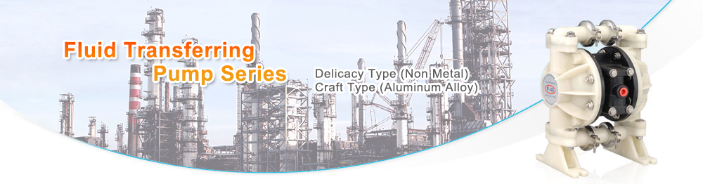
DF-40A CRAFT TYPE (ALUMINIUM ALLOY)
I. GENERAL DESCRIPTIONS :
- The pneumatic double diaphragms pump utilizes the air-driven principle with high safety measurement. It does not generate any sparks and resists to explosions.
- The pneumatic valve is adopted to meet ISO 5599/1 specifications and no lubrication oil required after long hours of operation.
- Wide range of applications: Polyurethane paint, UV curing, inks, and etc.
- Compact, light weight, portable, simple operations and easy to change paints. Applicable to different types of storage tanks.
II. SPECIFICATIONS:
Fluid rate: 45 liters/min
Pressure ratio: 1:1
Used air pressure: 1.5~3kg/cm2
Max.pressure: 7kg/cm2
III. INSTALATIONS:
- The pump can be wall, cart, stand, or pail mounted.
- The air inlet must be installed with the air cleaner to prevent dirt from entering into the air pilot valve and damaging components.
- Employ single pipe and prevent dead angles in order to maintain smooth transporting.
IV. HOW TO OPERATE :
- Adjust the operating pressure accordingly to the transporting range.
- The operating pressure cannot be less than 1.5kg/cm2. If there is a shortage of air pressure, the pump will not be operated smoothly and it can possibly cause pump to be clogged.
- The piping system must be cleaned after the work daily. Especially, when the pump is used for heavy viscosity painting. It is highly recommended that pumps should be cleaned completely for clog-free operation afterward.
V. TROUBLE SHOOTING :
- In the case of disassembling the pump for maintenance, shut the air inlet or release it and the paint outlet must be released as well.
- Do not operate pumps under the following conditions:
- Pumps are clogged.
- Diaphragms are damaged.
- Possible causes when there is no suction force:
- The ball seat is clogged at suction orifice.
- The suction pipe is damaged, which can reduce paint spraying smoothness.
- The pump has not been operated for a long time and the paint becomes hardened.
VI. PARTS LIST :
- Pump body
- Inlet nozzle of pilot valve
- Pneumatic pilot valve
- Screw
- Nipple
- Presure gauge
- Cock
- Pressure regulator
- Air inlet diaphragm
- shaft
- O ring
- Retaining ring
- V Packing
- Bushing (Bronze)
- O ring
- Retaining ring
- Gasket
- Fixed plate of diaphragm
- O ring
- Rubber diaphragm
- Teflon diaphragm
- O ring
- Fixed plate of diaphragm
- Screw nut
- Pressure stabilizing tank
- Counter-sink screw
- Manifold
- Plunger
- End cover
- Counter-sink screw
- Check valve
- Check valve post
- O ring
- Pin
- Plug
- Muffler
- Plug
- Manifold
- Plug
- Base
- Counter-sink screw
VII. DISASSEMBLY FIG :