Products
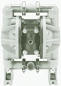
DF-40P AIR OPERATED DOUBLE DIAPHRAGM PUMP
I. PERFORMANCE CURVE :
II. DIMENSIONS :
III. SPECIFICATIONS:
Fluid rate: 45 liters/min
Pressure ratio: 1:1
Used air pressure: 1.5~3kg/cm2
Max.pressure: 7kg/cm2
IV. INSTALLATIONS :
- The pump can be wall, cart, stand, or pail mounted.
- The air inlet must be installed with the air cleaner to prevent dirt from entering into the air pilot valve and damaging components.
- Employ single pipe and prevent dead angles in order to maintain smooth transporting.
- The piping length should not exceed more than 10m to ensure proper pressure in transporting.
V. HOW TO OPERATE :
- Adjust the operating pressure accordingly to the transporting range.
- The operating pressure cannot be less than 1.5kg/cm2. If there is a shortage of air pressure, the pump will not be operated smoothly and it can possibly cause pump to be clogged.
- The piping system must be cleaned after the work daily. Especially, when the pump is used for heavy viscosity painting. It is highly recommended that pumps should be cleaned completely for clog-free operation afterward.
VI. TROUBLE SHOOTING :
- In the case of disassembling the pump for maintenance, shut the air inlet or release it and the paint outlet must be released as well.
- Do not operate pumps under the following conditions:
- Pumps are clogged.
- Diaphragms are damaged.
- Possible causes when there is no suction force:
- The ball seat is clogged at suction orifice.
- The suction pipe is damaged, which can reduce paint spraying smoothness.
- The pump has not been operated for a long time and the paint becomes hardened.
VII. PARTS LIST :
- End cover
- Washer
- Locking nut
- Inlet fitting
- Snap ring
- Air valve gasket
- Air valve screws
- Pump body
- Muffler plate gasket
- Shaft
- O ring
- Block bushing
- Screws
- Locking nut
- Elbow
- Muffler
- Locking nut
- Exhaust plate
- Gasket
- Screws
- Pump body
- O ring
- Washer
- Screws
- Valve body
- Piston cap
- O ring
- V ring
- Piston rod
- V ring
- Valve block
- Valve sheet
- O ring
- Rubber welt
- Rubber welt
- O ring
- Socket
- O ring
- Shaft
- Retaining ring
- O ring
- Retaining post
- Rubber welt
- Retaining sheet
- Snap ring
- Snap ring
- Rubber diaphragm
- Teflon diaphragm
- Telfon ball
- O ring
- O ring
- Socket
- Ball ost
- Outlet fitting
VIII. DISASSEMBLY FIG :